Real projective plane
In mathematics, the real projective plane, denoted or , is a two-dimensional projective space, similar to the familiar Euclidean plane in many respects but without the concepts of distance, circles, angle measure, or parallelism. It is the setting for planar projective geometry, in which the relationships between objects are not considered to change under projective transformations. The name projective comes from perspective drawing: projecting an image from one plane onto another as viewed from a point outside either plane, for example by photographing a flat painting from an oblique angle, is a projective transformation.
The fundamental objects in the projective plane are points and straight lines, and as in Euclidean geometry, every pair of points determines a unique line passing through both, but unlike in the Euclidean case in projective geometry every pair of lines also determines a unique point at their intersection (in Euclidean geometry, parallel lines never intersect). In contexts where there is no ambiguity, it is simply called the projective plane; the qualifier "real" is added to distinguish it from other projective planes such as the complex projective plane and finite projective planes.
One common model of the real projective plane is the space of lines in three-dimensional Euclidean space which pass through a particular origin point; in this model, lines through the origin are considered to be the "points" of the projective plane, and planes through the origin are considered to be the "lines" in the projective plane. These projective points and lines can be pictured in two dimensions by intersecting them with any arbitrary plane not passing through the origin; then the parallel plane which does pass through the origin (a projective "line") is called the line at infinity. (See § Homogeneous coordinates below.)
 The fundamental polygon of the projective plane – A is identified with A and B is identified with B, each with a twist |
 The Möbius strip – because of the twist between the identified red A sides of the square, the dotted line is a single edge
|
In topology, the name real projective plane is applied to any surface which is topologically equivalent to the real projective plane. Topologically, the real projective plane is compact and non-orientable (one-sided). It cannot be embedded in three-dimensional Euclidean space without intersecting itself. It has Euler characteristic 1, hence a demigenus (non-orientable genus, Euler genus) of 1.
The topological real projective plane can be constructed by taking the (single) edge of a Möbius strip and gluing it to itself in the correct direction, or by gluing the edge to a disk. Alternately, the real projective plane can be constructed by identifying each pair of opposite sides of the square, but in opposite directions, as shown in the diagram. (Performing any of these operations in three-dimensional space causes the surface to intersect itself.)
Examples
[edit]Projective geometry is not necessarily concerned with curvature and the real projective plane may be twisted up and placed in the Euclidean plane or 3-space in many different ways.[1] Some of the more important examples are described below.
The projective plane cannot be embedded (that is without intersection) in three-dimensional Euclidean space. The proof that the projective plane does not embed in three-dimensional Euclidean space goes like this: Assuming that it does embed, it would bound a compact region in three-dimensional Euclidean space by the generalized Jordan curve theorem. The outward-pointing unit normal vector field would then give an orientation of the boundary manifold, but the boundary manifold would be the projective plane, which is not orientable. This is a contradiction, and so our assumption that it does embed must have been false.
The projective sphere
[edit]Consider a sphere, and let the great circles of the sphere be "lines", and let pairs of antipodal points be "points". It is easy to check that this system obeys the axioms required of a projective plane:
- any pair of distinct great circles meet at a pair of antipodal points; and
- any two distinct pairs of antipodal points lie on a single great circle.
If we identify each point on the sphere with its antipodal point, then we get a representation of the real projective plane in which the "points" of the projective plane really are points. This means that the projective plane is the quotient space of the sphere obtained by partitioning the sphere into equivalence classes under the equivalence relation ~, where x ~ y if y = x or y = −x. This quotient space of the sphere is homeomorphic with the collection of all lines passing through the origin in R3.
The quotient map from the sphere onto the real projective plane is in fact a two sheeted (i.e. two-to-one) covering map. It follows that the fundamental group of the real projective plane is the cyclic group of order 2; i.e., integers modulo 2. One can take the loop AB from the figure above to be the generator.
Projective hemisphere
[edit]
Because the sphere covers the real projective plane twice, the plane may be represented as a closed hemisphere around whose rim opposite points are identified.[2]
Boy's surface – an immersion
[edit]The projective plane can be immersed (local neighbourhoods of the source space do not have self-intersections) in 3-space. Boy's surface is an example of an immersion.
Polyhedral examples must have at least nine faces.[3]
Roman surface
[edit]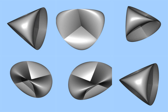
Steiner's Roman surface is a more degenerate map of the projective plane into 3-space, containing a cross-cap.

A polyhedral representation is the tetrahemihexahedron,[4] which has the same general form as Steiner's Roman surface, shown here.
Hemi polyhedra
[edit]Looking in the opposite direction, certain abstract regular polytopes – hemi-cube, hemi-dodecahedron, and hemi-icosahedron – can be constructed as regular figures in the projective plane; see also projective polyhedra.
Planar projections
[edit]Various planar (flat) projections or mappings of the projective plane have been described. In 1874 Klein described the mapping:[1]
Central projection of the projective hemisphere onto a plane yields the usual infinite projective plane, described below.
Cross-capped disk
[edit]A closed surface is obtained by gluing a disk to a cross-cap. This surface can be represented parametrically by the following equations:
where both u and v range from 0 to 2π.
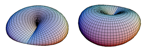
These equations are similar to those of a torus. Figure 1 shows a closed cross-capped disk.
|
| Figure 1. Two views of a cross-capped disk. |
A cross-capped disk has a plane of symmetry that passes through its line segment of double points. In Figure 1 the cross-capped disk is seen from above its plane of symmetry z = 0, but it would look the same if seen from below.
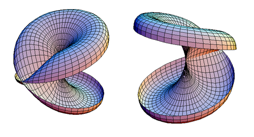
A cross-capped disk can be sliced open along its plane of symmetry, while making sure not to cut along any of its double points. The result is shown in Figure 2.
|
| Figure 2. Two views of a cross-capped disk which has been sliced open. |
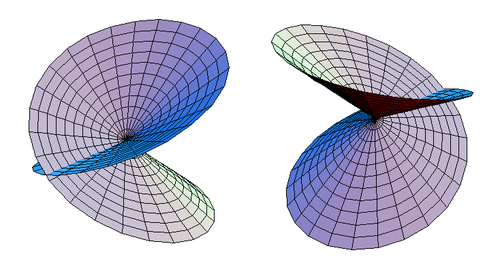
Once this exception is made, it will be seen that the sliced cross-capped disk is homeomorphic to a self-intersecting disk, as shown in Figure 3.
|
| Figure 3. Two alternative views of a self-intersecting disk. |
The self-intersecting disk is homeomorphic to an ordinary disk. The parametric equations of the self-intersecting disk are:
where u ranges from 0 to 2π and v ranges from 0 to 1.
Projecting the self-intersecting disk onto the plane of symmetry (z = 0 in the parametrization given earlier) which passes only through the double points, the result is an ordinary disk which repeats itself (doubles up on itself).
The plane z = 0 cuts the self-intersecting disk into a pair of disks which are mirror reflections of each other. The disks have centers at the origin.
Now consider the rims of the disks (with v = 1). The points on the rim of the self-intersecting disk come in pairs which are reflections of each other with respect to the plane z = 0.
A cross-capped disk is formed by identifying these pairs of points, making them equivalent to each other. This means that a point with parameters (u, 1) and coordinates is identified with the point (u + π, 1) whose coordinates are . But this means that pairs of opposite points on the rim of the (equivalent) ordinary disk are identified with each other; this is how a real projective plane is formed out of a disk. Therefore, the surface shown in Figure 1 (cross-cap with disk) is topologically equivalent to the real projective plane RP2.
Homogeneous coordinates
[edit]The points in the plane can be represented by homogeneous coordinates. A point has homogeneous coordinates [x : y : z], where the coordinates [x : y : z] and [tx : ty : tz] are considered to represent the same point, for all nonzero values of t. The points with coordinates [x : y : 1] are the usual real plane, called the finite part of the projective plane, and points with coordinates [x : y : 0], called points at infinity or ideal points, constitute a line called the line at infinity. (The homogeneous coordinates [0 : 0 : 0] do not represent any point.)
The lines in the plane can also be represented by homogeneous coordinates. A projective line corresponding to the plane ax + by + cz = 0 in R3 has the homogeneous coordinates (a : b : c). Thus, these coordinates have the equivalence relation (a : b : c) = (da : db : dc) for all nonzero values of d. Hence a different equation of the same line dax + dby + dcz = 0 gives the same homogeneous coordinates. A point [x : y : z] lies on a line (a : b : c) if ax + by + cz = 0. Therefore, lines with coordinates (a : b : c) where a, b are not both 0 correspond to the lines in the usual real plane, because they contain points that are not at infinity. The line with coordinates (0 : 0 : 1) is the line at infinity, since the only points on it are those with z = 0.
Points, lines, and planes
[edit]A line in P2 can be represented by the equation ax + by + cz = 0. If we treat a, b, and c as the column vector ℓ and x, y, z as the column vector x then the equation above can be written in matrix form as:
- xTℓ = 0 or ℓTx = 0.
Using vector notation we may instead write x ⋅ ℓ = 0 or ℓ ⋅ x = 0.
The equation k(xTℓ) = 0 (which k is a non-zero scalar) sweeps out a plane that goes through zero in R3 and k(x) sweeps out a line, again going through zero. The plane and line are linear subspaces in R3, which always go through zero.
Ideal points
[edit]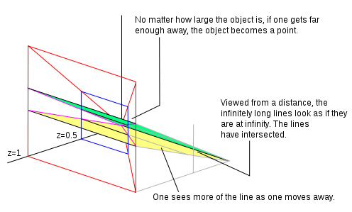
In P2 the equation of a line is ax + by + cz = 0 and this equation can represent a line on any plane parallel to the x, y plane by multiplying the equation by k.
If z = 1 we have a normalized homogeneous coordinate. All points that have z = 1 create a plane. Let's pretend we are looking at that plane (from a position further out along the z axis and looking back towards the origin) and there are two parallel lines drawn on the plane. From where we are standing (given our visual capabilities) we can see only so much of the plane, which we represent as the area outlined in red in the diagram. If we walk away from the plane along the z axis, (still looking backwards towards the origin), we can see more of the plane. In our field of view original points have moved. We can reflect this movement by dividing the homogeneous coordinate by a constant. In the adjacent image we have divided by 2 so the z value now becomes 0.5. If we walk far enough away what we are looking at becomes a point in the distance. As we walk away we see more and more of the parallel lines. The lines will meet at a line at infinity (a line that goes through zero on the plane at z = 0). Lines on the plane when z = 0 are ideal points. The plane at z = 0 is the line at infinity.
The homogeneous point (0, 0, 0) is where all the real points go when you're looking at the plane from an infinite distance, a line on the z = 0 plane is where parallel lines intersect.
Duality
[edit]
In the equation xTℓ = 0 there are two column vectors. You can keep either constant and vary the other. If we keep the point x constant and vary the coefficients ℓ we create new lines that go through the point. If we keep the coefficients constant and vary the points that satisfy the equation we create a line. We look upon x as a point, because the axes we are using are x, y, and z. If we instead plotted the coefficients using axis marked a, b, c points would become lines and lines would become points. If you prove something with the data plotted on axis marked x, y, and z the same argument can be used for the data plotted on axis marked a, b, and c. That is duality.
Lines joining points and intersection of lines (using duality)
[edit]The equation xTℓ = 0 calculates the inner product of two column vectors. The inner product of two vectors is zero if the vectors are orthogonal. In P2, the line between the points x1 and x2 may be represented as a column vector ℓ that satisfies the equations x1Tℓ = 0 and x2Tℓ = 0, or in other words a column vector ℓ that is orthogonal to x1 and x2. The cross product will find such a vector: the line joining two points has homogeneous coordinates given by the equation x1 × x2. The intersection of two lines may be found in the same way, using duality, as the cross product of the vectors representing the lines, ℓ1 × ℓ2.
Embedding into 4-dimensional space
[edit]The projective plane embeds into 4-dimensional Euclidean space. The real projective plane P2(R) is the quotient of the two-sphere
- S2 = {(x, y, z) ∈ R3 : x2 + y2 + z2 = 1}
by the antipodal relation (x, y, z) ~ (−x, −y, −z). Consider the function R3 → R4 given by (x, y, z) ↦ (xy, xz, y2 − z2, 2yz). This map restricts to a map whose domain is S2 and, since each component is a homogeneous polynomial of even degree, it takes the same values in R4 on each of any two antipodal points on S2. This yields a map P2(R) → R4. Moreover, this map is an embedding. Notice that this embedding admits a projection into R3 which is the Roman surface.
Higher non-orientable surfaces
[edit]By gluing together projective planes successively we get non-orientable surfaces of higher demigenus. The gluing process consists of cutting out a little disk from each surface and identifying (gluing) their boundary circles. Gluing two projective planes creates the Klein bottle.
The article on the fundamental polygon describes the higher non-orientable surfaces.
See also
[edit]- Real projective space
- Projective space
- Pu's inequality for real projective plane
- Smooth projective plane
Citations
[edit]- ^ a b Apéry 1987
- ^ Weeks 2002, p. 59
- ^ Brehm 1990, pp. 51–56
- ^ Richter
References
[edit]- Apéry, F. (1987), Models of the real projective plane, Vieweg
- Brehm, U. (1990), "How to build minimal polyhedral models of the Boy surface", The Mathematical Intelligencer, 12 (4): 51–56, doi:10.1007/BF03024033, S2CID 120093360
- Coxeter, H.S.M. (1955), The Real Projective Plane (2nd ed.), Cambridge: At the University Press
- Baer, Reinhold (2005), Linear Algebra and Projective Geometry, Dover, ISBN 0-486-44565-8
- Richter, David A., Two Models of the Real Projective Plane, retrieved 2010-04-15
- Weeks, J. (2002), The shape of space, CRC


